UML Diagrams
A: UML is a modelling language. UML means Unified Modelling Language used by software engineers / analysts over the ages to defines the different goals of the product to be designed.
In other word’s UML is a standardized modeling language enabling developers to specify, visualize, construct and document artifacts of a software system. Thus, UML makes these artifacts scalable, secure and robust in execution. UML is an important aspect involved in object-oriented software development.
Q. What is the use of UML in software engineering?
A: UML is used in object oriented software engineering. Although typically used in software engineering it is a rich language that can be used to model an application structures, behavior and even business processes.
Q. What is the purpose of a UML diagram?
A: A UML class diagram is not only used to describe the object and information structures in an application, but also show the communication with its users. It provides a wide range of usages; from modeling the static view of an application to describing responsibilities for a system.
Q. What are the tools of UML?
A: A UML tool or UML modeling tool is a software application that supports some or all of the notation and semantics associated with the Unified Modeling Language (UML), which is the industry standard general purpose modeling language for software engineering. UML tool is used broadly here to include application programs which are not exclusively focused on UML, but which support some functions of the Unified Modeling Language, either as an add-on, as a component or as a part of their overall functionality.
Q. List of UML tools.
A: There are lot of tools used for UML below are some of them popular most,
- Microsoft Visio.
- Modelio.
- PlantUML.
- Dia.
Q. Types of UML diagrams.
A: Below are the types of UML diagrams,
- Structural UML diagram:
- Class diagram.
- Component diagram.
- Composite Structure diagram.
- Deployment diagram.
- Object diagram.
- Package diagram.
- Profile diagram.
- Behavioral UML diagram:
- Activity diagram.
- Communication diagram.
- Interaction overview diagram.
- Sequence diagram.
- State diagram.
- Timing diagram.
- Use Case diagram.
Below are certain diagrams of UML that are used day to day by an Business Analyst,
- Class Diagram:
- Deployment Diagram:
- Device Node
- Execution Environment Node
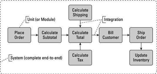
- Activity diagram:
- rounded rectangles represent actions;
- diamonds represent decisions;
- bars represent the start (split) or end (join) of concurrent activities;
- a black circle represents the start (initial node) of the workflow;
- an encircled black circle represents the end (final node).
- Arrows run from the start towards the end and represent the order in which activities happen.
- Sequence diagram:
- Use case diagram:
- State Diagram:
In software engineering, a class diagram in the Unified Modeling Language (UML) is a type of static structure diagram that describes the structure of a system by showing the system's classes, their attributes, operations (or methods), and the relationships among objects. The class diagram is the main building block of object-oriented modelling. It is used for general conceptual modelling of the systematic of the application, and for detailed modelling translating the models into programming code. Class diagrams can also be used for data modeling. The classes in a class diagram represent both the main elements, interactions in the application, and the classes to be programmed.
A class with three compartments.

In the diagram, classes are represented with boxes that contain three compartments:
The top compartment contains the name of the class. It is printed in bold and centered, and the first letter is capitalized.
The middle compartment contains the attributes of the class. They are left-aligned and the first letter is lowercase.
The bottom compartment contains the operations the class can execute. They are also left-aligned and the first letter is lowercase.
E.g. Class diagram showing generalization between the superclass Person and the two subclasses Student and Professor

Class diagram showing dependency between "Car" class and "Wheel" class (An even clearer example would be "Car depends on Wheel", because Car already aggregates (and not just uses) Wheel)

A deployment diagram in the Unified Modeling Language models the physical deployment of artifacts on nodes. To describe a web site, for example, a deployment diagram would show what hardware components ("nodes") exist (e.g., a web server, an application server, and a database server), what software components ("artifacts") run on each node (e.g., web application, database), and how the different pieces are connected (e.g. JDBC, REST, RMI).
The nodes appear as boxes, and the artifacts allocated to each node appear as rectangles within the boxes. Nodes may have subnodes, which appear as nested boxes. A single node in a deployment diagram may conceptually represent multiple physical nodes, such as a cluster of database servers. There are two types of Nodes:
Device nodes are physical computing resources with processing memory and services to execute software, such as typical computers or mobile phones. An execution environment node (EEN) is a software computing resource that runs within an outer node and which itself provides a service to host and execute other executable software elements.

Activity diagrams are graphical representations of workflows of stepwise activities and actions with support for choice, iteration and concurrency. In the Unified Modeling Language, activity diagrams are intended to model both computational and organizational processes (i.e. workflows). Activity diagrams show the overall flow of control.
Activity diagrams are constructed from a limited number of shapes, connected with arrows. The most important shape types:

A sequence diagram is an interaction diagram that shows how objects operate with one another and in what order. It is a construct of a message sequence chart.
A sequence diagram shows object interactions arranged in time sequence. It depicts the objects and classes involved in the scenario and the sequence of messages exchanged between the objects needed to carry out the functionality of the scenario. Sequence diagrams are typically associated with use case realizations in the Logical View of the system under development. Sequence diagrams are sometimes called event diagrams or event scenarios.
A sequence diagram shows, as parallel vertical lines (lifelines), different processes or objects that live simultaneously, and, as horizontal arrows, the messages exchanged between them, in the order in which they occur. This allows the specification of simple runtime scenarios in a graphical manner.
E.g: Sequence diagram of e-mail message sequence

A use case diagram at its simplest is a representation of a user's interaction with the system that shows the relationship between the user and the different use cases in which the user is involved. A use case diagram can identify the different types of users of a system and the different use cases and will often be accompanied by other types of diagrams as well.
E.g: A UML use case diagram for the interaction of a client (the actor) within a restaurant (the system)

UML preserves the general form of the traditional state diagrams. The UML state diagrams are directed graphs in which nodes denote states and connectors denote state transitions.
For example, Figure 1 shows a UML state diagram corresponding to the computer keyboard state machine. In UML, states are represented as rounded rectangles labeled with state names. The transitions, represented as arrows, are labeled with the triggering events followed optionally by the list of executed actions. The initial transition originates from the solid circle and specifies the default state when the system first begins. Every state diagram should have such a transition, which should not be labeled, since it is not triggered by an event. The initial transition can have associated actions.

Additional web references:
Tutorials Point
UML Diagram Types
UML Diagrams
. Note: The content on this page is a collection of data from various websites.

Thanks for sharing the best information and suggestions, it is very nice and very useful to us. I appreciate the work that you have shared in this post. Keep sharing these types of articles here.
ReplyDeleteManagement Consulting In Sydney
Wcontferlia-do German Cirulis https://wakelet.com/wake/E_OoMSF_hNcCUMihkpQLG
ReplyDeletenabseiteti
OcisciYam-ze Cyndi Peacock click
ReplyDeleteDownload Free
kizrisoper
ReplyDeleteUnified Modeling Language (UML) is a visual representation tool vital in software engineering. How Better Get Its standardized notations enable clear communication among stakeholders, streamlining the development.